
I took a look at their CAD file and it looked pretty standard, and didn’t find anything wrong with it. But when I opened the file in Navisworks this is what I saw.


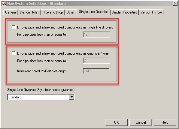
The view settings on the Navisworks end looked fine, so I went back to the DWG in AutoCAD MEP and dug a little deeper. As it turned out, the office CAD standards specified that all piping less than 12" diameter would be represented as a single line. The setting can be found in the Pipe System Definition and affects all views including any view in and out of AutoCAD, such as Navisworks. I opened up the Pipe System Definition for that pipe and and unchecked the single line display boxes under the Single Line Graphics tab; saved the drawing and brought it back into Navisworks. Everything looked good. All MEP content, including pipe, were now displaying as 3D.

 Derek Wielkopolski
Technical Support Manager/Application Specialist
Derek holds a Bachelor of Architecture degree from Roger Williams University, Rhode Island. He is experienced working within the AEC industry from concept design through construction administration for both small and large scale projects. As Ideate’s Support Manager he ensures a timely and quality response to support requests and questions. Follow Derek on Twitter: @dwielk
Get it. Know it. Use it.